Preventive Maintenance
This section provides information on performing preventive maintenance on the BD MAX instrument.
BD MAX™ System User’s Manual References:
- International Windows Version - Document No. 8089570
- US Open System Windows Version - Document No. 8089571
- US Open System Windows Version -Document No. 8089571
For service compliance reasons, always confirm that the document is the most current revision available in SAP. Contact the BD MAX System Support Specialist (SSS) or Technical Education Specialist for additional information if needed.
Associated Procedures:
Materials
| Item | SAP | Qty |
|---|---|---|
| PM Kit | 435253 | 1 |
| Service Alignment Tool Kit | 441998 | 1 |
| Qualification Kit (1 backup) | 444048 | 2 |
| Load Cartridge Test Kit | 445028 | 1 |
| Box of 24 Cartridges | 437519 | 1 |
| Calibration Plate | 435251 | 1 |
| Calibration Plate 6 Color | 435256 | 1 |
| Multi Meter | ||
| #10 Torx Security driver | ||
| Assorted Hand Tools (Metric and Standard) | ||
| Ultra-fine Scotch-Brite Pad (7448 or equivalent) |
The BD MAX instrument uses electrical voltage and power levels that are potentially lethal. During normal operations, these voltages are internal to the instrument and do not present a hazard. However, while testing, troubleshooting, and performing maintenance, it is sometimes necessary to remove parts of the instrument enclosure exposing electrically charged circuits. When the High Voltage symbol appears in this procedure, use safety precautions.
The BD MAX instrument contains Electro Static Discharge (ESD) sensitive components. When servicing the instrument, ESD protection must be utilized to prevent possible damage to sensitive components. Failure to follow proper ESD precautions can induce intermittent and/or catastrophic failures. When the ESD Discharge symbol appears in this procedure, use proper ESD techniques.
All warnings and cautions should be observed while servicing BD MAX instrumentation. All discrepancies should be documented in Service Max and service personnel should always reference the latest service bulletins.
Procedure
- Open the instrument door and turn off the power to the instrument.
- Use the black nozzle block to keep the tips raised when moving the robot.
- Remove the front skirt by lifting it upwards at both ends and pulling away from the instrument. The front skirt contains the input air filter. Clean the air filter. If the filter (SAP 435226) is damaged, make arrangements to replace it.
- Remove the upper waterfall with the following steps:
- Ensure the instrument power is turned off
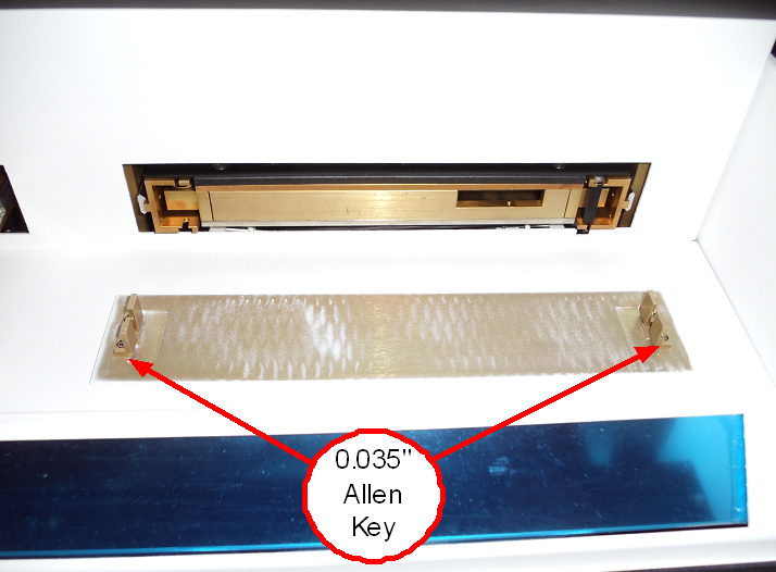
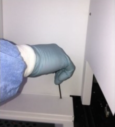
- Remove both tray covers using the 0.035” Allen key from the PM kit.
- Remove the five T10 torx screws from the top back of the rear upper reader cover.
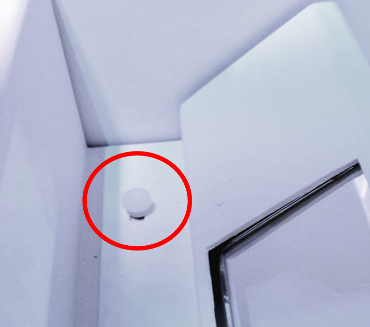
- Remove the two white nylon thumb screws just in front of the mirror and on the left and right sides.
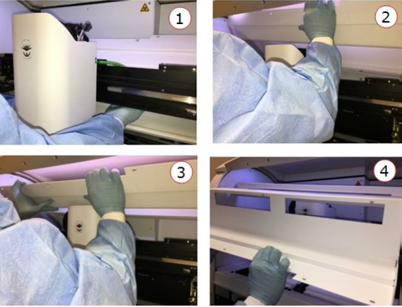
- Push the trays all the way in and pull the X gantry all the way to the front of the instrument.
- Slowly lift up the rear upper waterfall, moving the robot towards the back of the instrument as the cover it is rotated over the top of the robot.
- Remove the lower waterfall with the following steps:
- Remove the left and right front screws.
- Push the robot to the back of the instrument.
- Lift the front of the lower reader cover until the rear lip rotates below the mirror.
- Slowly lift the cover up and towards you, removing it from the instrument.
Static Sensitive Circuits and Dangerous Voltages are exposed once the covers are removed. Use appropriate ESD and Electrical Safety practices
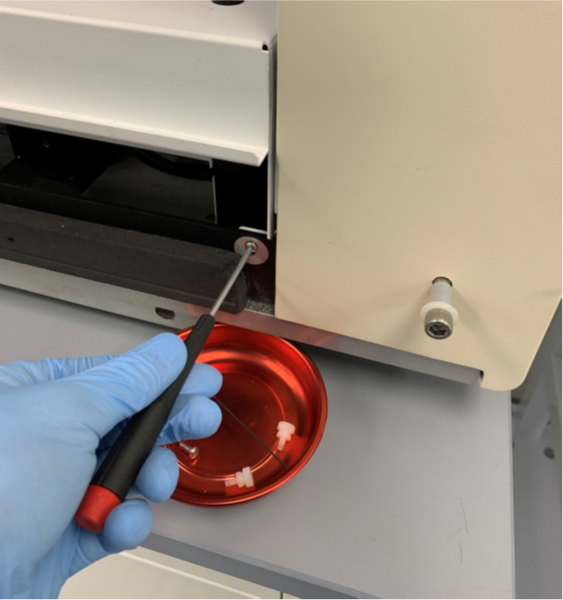
- Remove the left and right front screws.
-
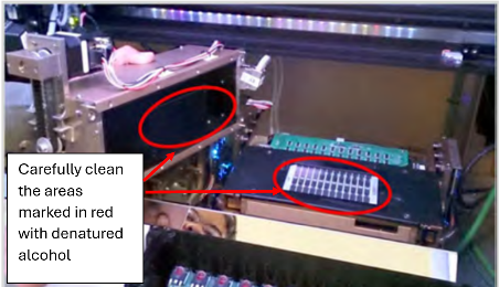
Remove each reader and use a lint-free cloth to clean the glass heater surface and the reader aperture plate for each reader. When cleaning, go along the aperture plate. Do not touch either the aperture plate or the Heater glass surface with your hands. Be careful not to damage the surface of the heater boards. Use denatured alcohol to remove more stubborn material.
-
Inspect moving parts for wear and loose hardware. If there is extensive wear and/or damage, make arrangements for replacements.
-
Tighten the 1/8 inch and 5/32 inch hex screws securing the door to each side wall.
-
Tighten the screws on and around each tray, especially near the rails.
-
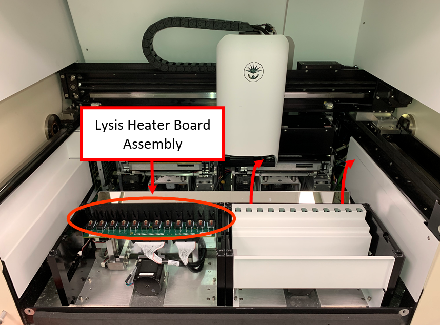
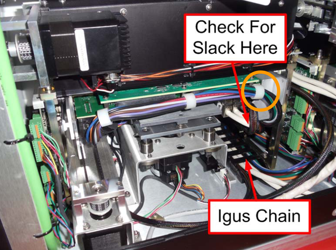
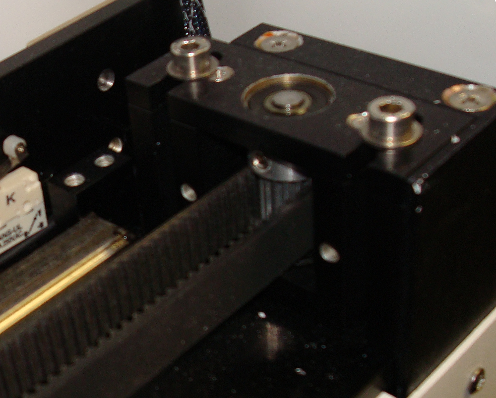
- Check the heater MUX boards' cable tension by moving the drawers in/out and up/down. The heater mux should fall straight down and rest on the metal tray. Observe if the cables and Igus chain are interfering with drawer movement and that the connections are secure.
-
For instruments with the white heater mux cable loops, check that the cables are not preventing the heater mux from moving up/down freely. Removing the cable loop (circled in orange) above the SCSI cable connections can alleviate tension.
-
If any strain or movement interference is noted, adjust the cable slack and positioning while moving the drawers in/out and up/down. Check the condition of the cable to make sure there are no signs of damage.
-
Inspect the rails for any signs of oxidation.
-
Remove any oxidation with an ultra-fine Scotch-Brite pad.
-
Clean off any residue with a lint free cloth.
-
- Lubricate moving parts:
Manually lubricate all rails with the lithium bearing grease. Make sure the back and front parts of the Y- and X-gantry rails are well lubricated, as these parts are outside of the Y- and X-axis travel and do not get lubrication during normal operations.
Pack the bearing carriages for the X- and Y- axis with the disposable grease gun (1 to 2 pumps). There are four of these, one on each side of the X gantry, that lubricates the Y- rails and one on the Z-Gantry that lubricates the X-rail.
Please change gloves before proceeding.
- Check the extractor magnet alignment for both sets of magnets.
- Check all airline connections on the Z-Head.
- Make arrangements to replace any worn or damaged air lines.
- Hands tighten as necessary.
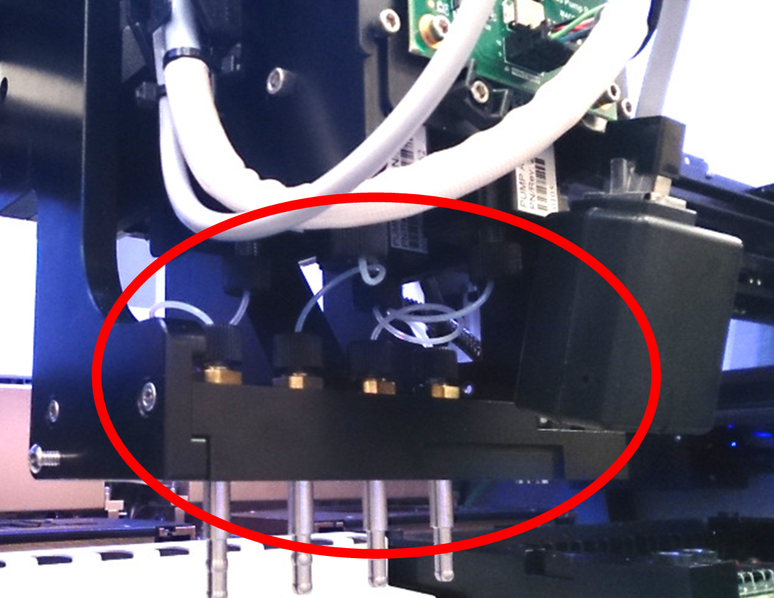
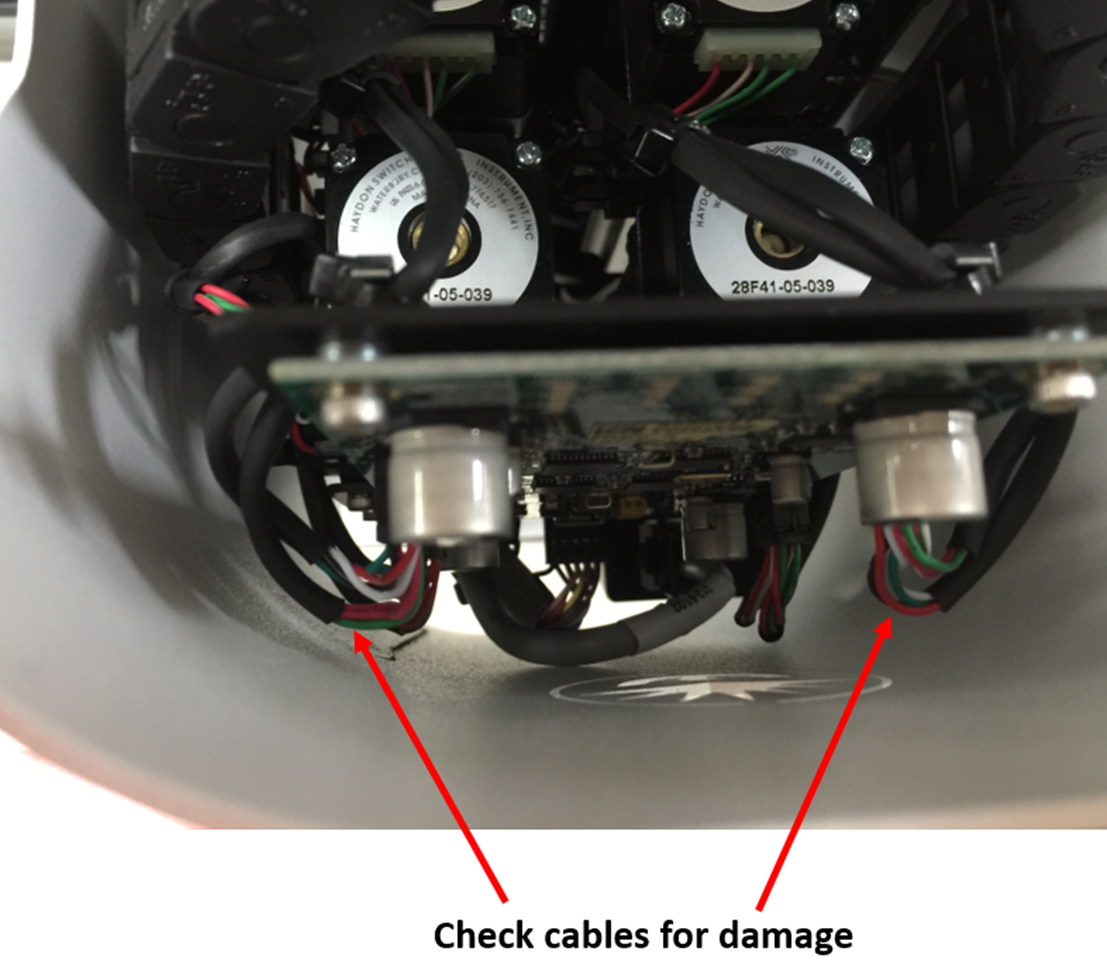
- Inspect cables on the Z-head for damage. Ensure they are not rubbing on the Z-head façade.
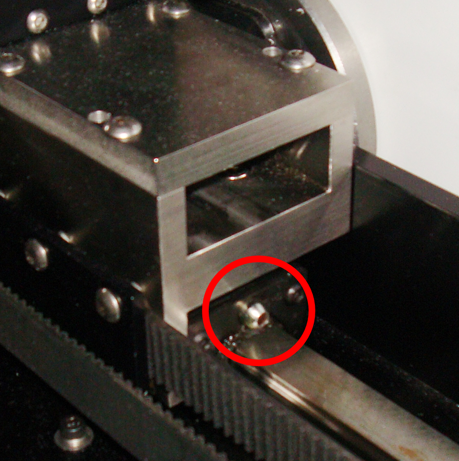
- Inspect Motor belt drive gears and idler gears on the X- and Y- gantries. If there is extensive wear and/or damage, make arrangements for replacements.
-
Visually inspect the X- and Y- gantry drive belts. If there is extensive wear and/or damage (tears, cracks, etc), make arrangements for replacements.
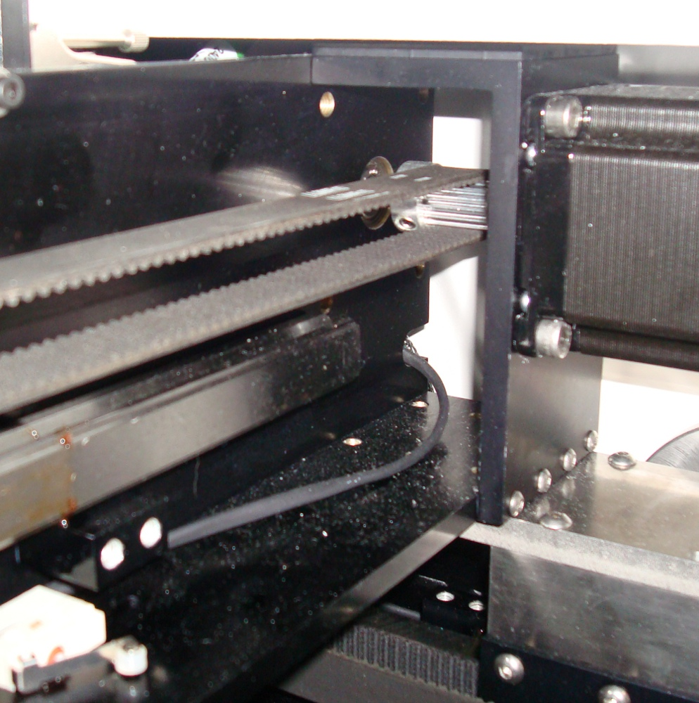
-
Check all rack sensors (SAP 435222) and ensure edges are not worn down or broken. If a sensor is broken or damaged, replace as needed.
- Perform extractor magnet alignment (see Extractor Magnet Alignment).
- Check overall cleanliness of instrument interior and exterior.
- DO NOT use canned or compressed air to clean out the instrument.
- Use a portable vacuum cleaner, lint free clothes, and denatured alcohol to clean the inside of the instrument if necessary.
-
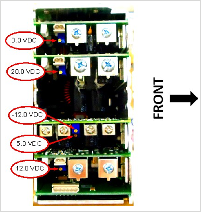
Turn instrument power on and measure the Power Supply Voltages on the Liberty board test points in front of the left reader as per next Table.
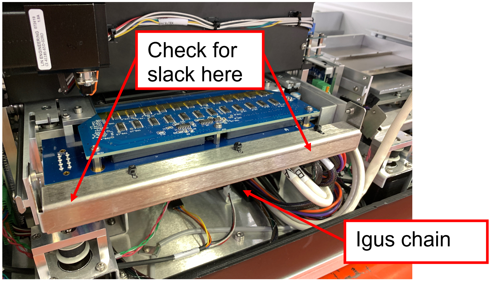

Table : Test points
| TP1 (GND) – TP3 (11.4Vdc to 12.6Vdc) |
| *TP1 (GND) – TP4 (5.13Vdc to 5.17Vdc) |
| *TP1 (GND) – TP5 (3.47Vdc to 3.49Vdc) |
| TP1 (GND) – TP6 (-11.4Vdc to -12.6Vdc) |
| TP2 (GND) – TP7 (19.0Vdc to 21.0Vdc) |
| TP2 (GND) – TP8 (22.8Vdc to 25.2Vdc) |
*Critical values
-
Adjust all out of specification voltages. See figure 8 for location of voltage adjustment potentiometers.
-
Re-assemble the instrument and remove the black nozzle block.
-
Perform gantry alignment using the calrack.script
Verification
Perform the following Verifications:
-
-
Confirm all parameter PASS at the end of the table.
-
-
-
Confirm the Barcodes are read with one clear Beep in the designated marked area.
-
-
-
Visual confirmation: The PCR cartridges are full.
-
-
-
Confirm the values are below 350. Cleaning is required if the range is 350 to 450.
-
-
Procedure Normalizer Ratio Check.
-
Confirm there is no renormalized message on the text. If needed, perform Procedure Reader Normalization.
-
- Perform full qualification run. Refer to 5-Channel Qualification Test.
After the Service/Installation activities have been completed, perform the specified verification to ensure the product performs as intended. Ensure that applicable results and inspection(s) have been documented per the instructions within the Service Manual. Complete the Technician sign-off statement accordingly within the Service Management System.